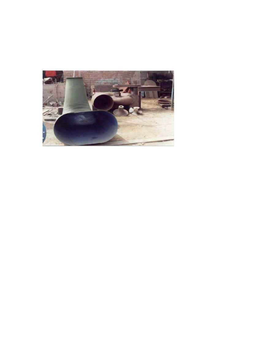
1.6 Suction tube
This is the component responsible for channelling the water after it passes by
the turbine wheel, as far as the outlet channel. The suction tube is used on
reaction-type turbines. (Fig. 3)
Figure 3: Suction tube manufactured from sheet steel
1.7 Transmission
This system is responsible for transmitting the movement and mechanical
power of the turbine to the generator. As a result of design conditions, the
speed of the turbine (900 r.p.m.) does not coincide with the speed of the
generator (1800 r.p.m.), meaning that the speed needs to be stepped up. In
this case a flexible transmission system is employed, using belts and pulleys:
3 trapezoidal belts, a guided 8-inch diameter pulley on the generator axle
and a 16-inch diameter drive pulley fitted to the turbine axle.
1.8Valve
The valve serves to control the flow of water. For this axial turbine a 600 mm
diameter gate-type valve has been produced, to be fitted upstream of the
intake of water into the turbine. (Fig. 4)
1.9Dresser coupling
This device serves to connect the turbine to the pressure pipes, and is
therefore referred to as a mounting joint. This